Figuring out the GEM Gemini amp circuit
I wrote this back in 2023 and never posted it. Not sure why.
I have a few 60s GEM organs in various states of disrepair. One thing that usually helps to sort them out is to replace any electrolytic capacitors that are bulging or leaking, usually around the power and amplifier circuits. I’ve done this a few times, and started to get curious about how the amplifier circuit actually works.
It’s a little tricky to learn, because the way the organ companies built amps in the early to mid 60s kept changing as transistor technology improved. And this history is sprinkled around the more obscure corners of the internet — organ repair forums and mailing lists, PDFs of self-published textbooks by organ engineers and dodgy scans of the paper schematics that manufacturers provided to help people repair and maintain their instruments.
So anything I think I know now is probably at least half wrong. But I wanted to write it up as a note to my future self if nothing else.
Research
I’m working on a GEMini (aka. Gemini, aka. Gem Mini), the cuter and smaller GEM model from the Italian Galanti company, who also made Vox and Eko instruments. I have three of these, and the circuit for each one is a little different. They just kept tweaking, and any schematic you find (even the printed schematic I found rolled up inside my GEM Jumbo) is likely to be somewhat innacurate.
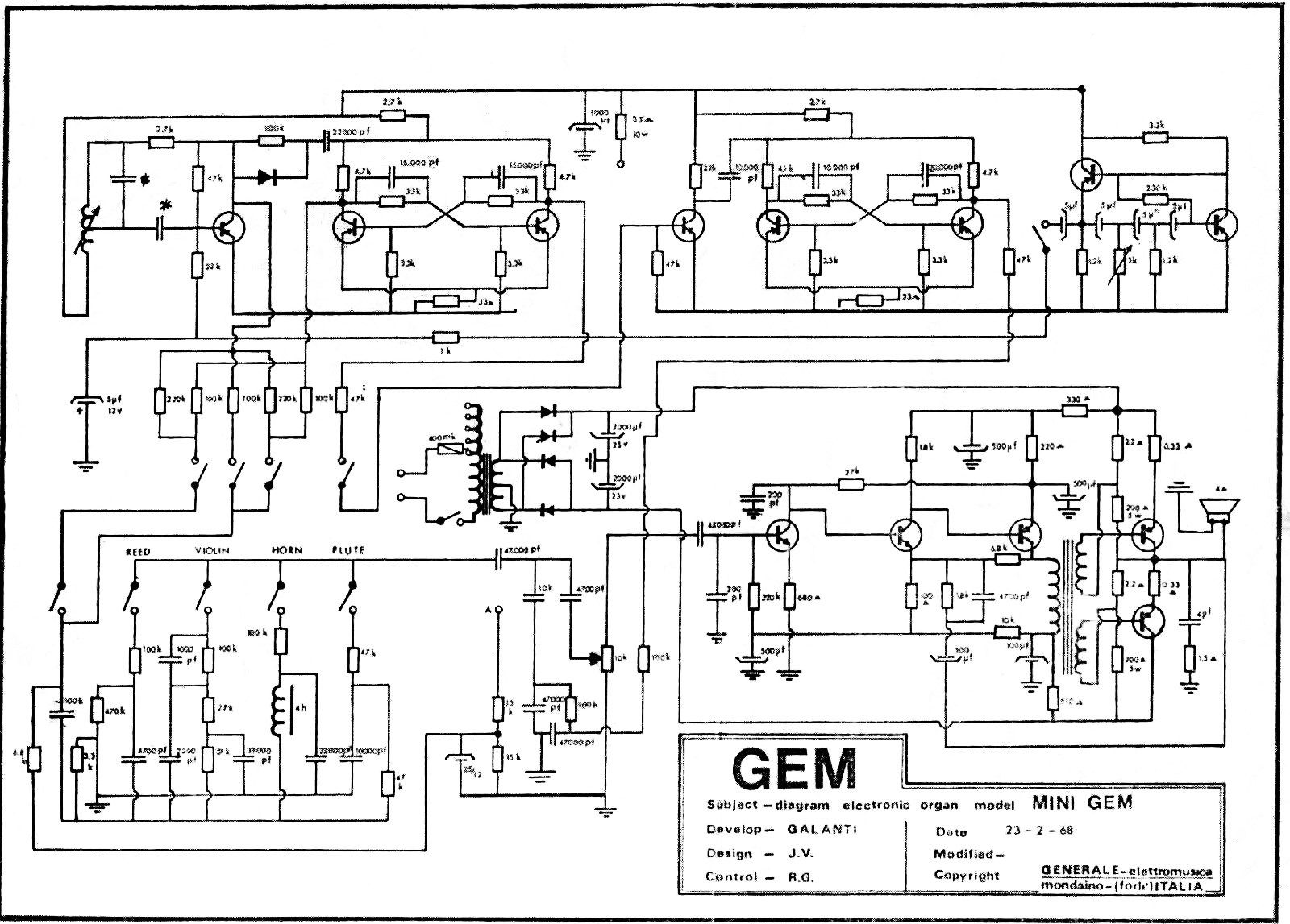
But the schematics are still very useful as a starting point. I had two that seemed similar, for the Mini:
And the Jumbo:
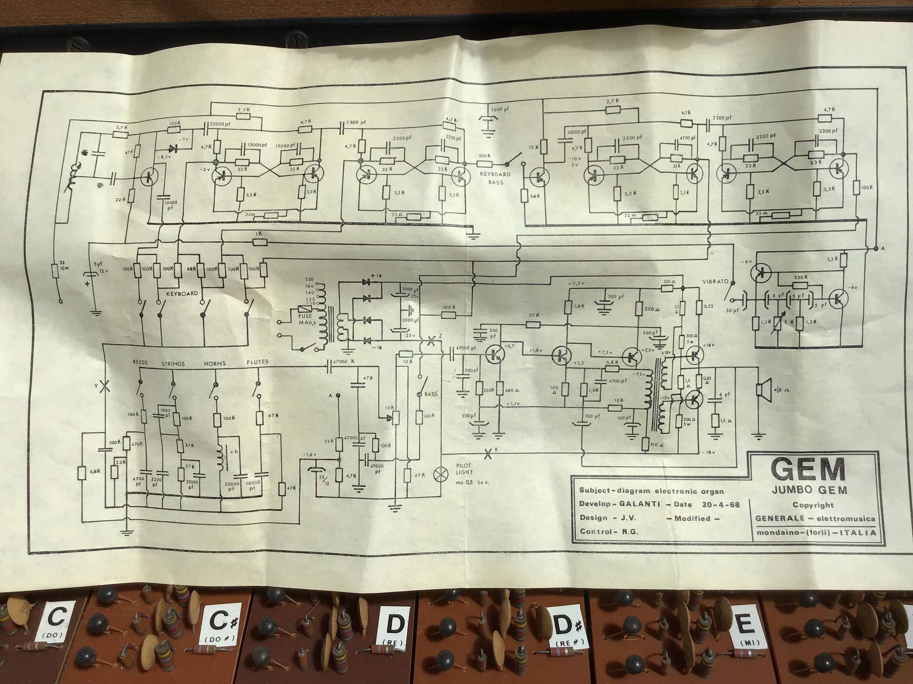
The amplifier circuits (bottom right, the part with 5 transistors and a transformer) are almost identical, but with a bunch of slightly different component values that make it hard to match the resistors and capacitors on the board to the schematic without tracing it all out. So that’s what I did.
Schematic
Here’s the schematic for the amp board on this particular GEMini, which is probably subtly different to yours (pdf version):
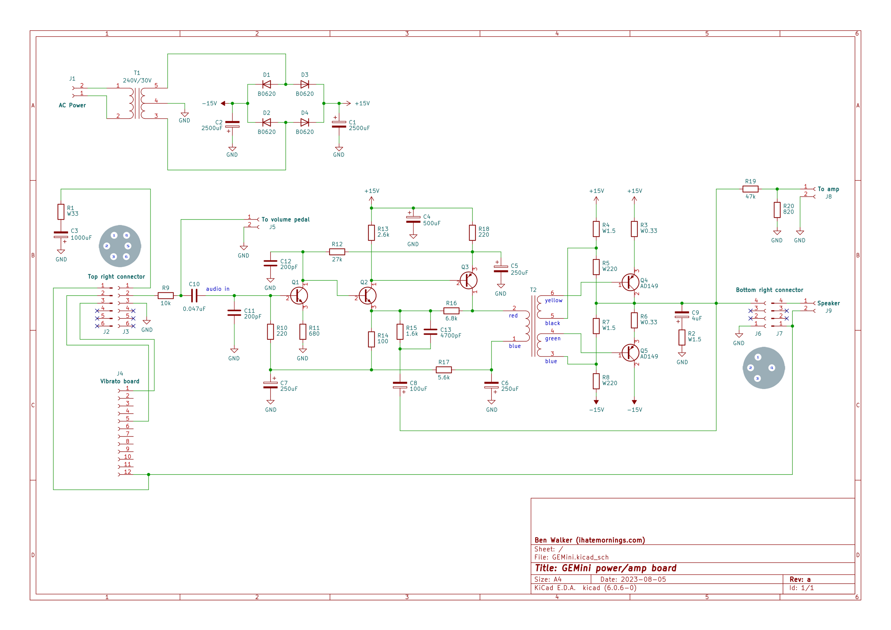
The left hand side with the three transistors is the pre-amp section, and looks quite familiar. The part that I struggle to wrap my head around is the transformer with two secondary windings that feeds the output transistors. I’ve seen amp designs where that sort of transformer feeds a matched pair of NPN and PNP transistors, with one amplifying the positive swing of the audio and the other amplifying the negative, but in this case both transistors are PNP.
I assume there’s something clever going on where the biasing of the transistors and the phase of the incoming signals means that both halves of the audio signal are amplified, but my mental model of PNP transistors isn’t quite there yet. Time to do some more reading…