on permanence: album art as aesthetic object
When I was in Pittsburgh last weekend I bought several beautiful books, one of them being a book length essay by Laura Lopez Paniagua called Mike Kelley: Materialist Aesthetics and Memory Illusions. In it she says there is no way to separate an object from the way it appears, and that’s what I’m trying to get at. Music can sometimes be just auditory experiences. Albums cannot. Albums are objects — pieces that are inextricable from the visual art you experience it with. That doesn’t mean it’s static, but it does feel permanent.
I think this might be the reason I’m obsessed with listening to albums, never single tracks or playlists. Albums feel different, they mean more, and that’s partly because they have a visual identity — I know what they look like.
We should resist the urge to data-fy and commodify our personal websites. Unintuitively, that means smaller, more closed communities and networks where communication is intentional rather than automated and surveilled. You’ll never know everything about your website, or its readers, and nor should you.
Analytics are always tempting, like play stats, but I think this post has a point — they don’t actually mean anything outside of business.
The Age of the Double Sell-Out
The 20th century taboo against selling out was, at its heart, a communal norm to reward young artists who focused on craft and punish those who appropriated art and subculture for empty profiteering. Now the culture is most exemplified by people whose entire end goal appears to be empty profiteering.
True. But also in my experience young artists don’t really have much opportunity to sell out (or even make any money at all) these days.
Figuring out the GEM Gemini amp circuit
I wrote this back in 2023 and never posted it. Not sure why.
I have a few 60s GEM organs in various states of disrepair. One thing that usually helps to sort them out is to replace any electrolytic capacitors that are bulging or leaking, usually around the power and amplifier circuits. I’ve done this a few times, and started to get curious about how the amplifier circuit actually works.
It’s a little tricky to learn, because the way the organ companies built amps in the early to mid 60s kept changing as transistor technology improved. And this history is sprinkled around the more obscure corners of the internet — organ repair forums and mailing lists, PDFs of self-published textbooks by organ engineers and dodgy scans of the paper schematics that manufacturers provided to help people repair and maintain their instruments.
So anything I think I know now is probably at least half wrong. But I wanted to write it up as a note to my future self if nothing else.
Research
I’m working on a GEMini (aka. Gemini, aka. Gem Mini), the cuter and smaller GEM model from the Italian Galanti company, who also made Vox and Eko instruments. I have three of these, and the circuit for each one is a little different. They just kept tweaking, and any schematic you find (even the printed schematic I found rolled up inside my GEM Jumbo) is likely to be somewhat innacurate.
But the schematics are still very useful as a starting point. I had two that seemed similar, for the Mini:
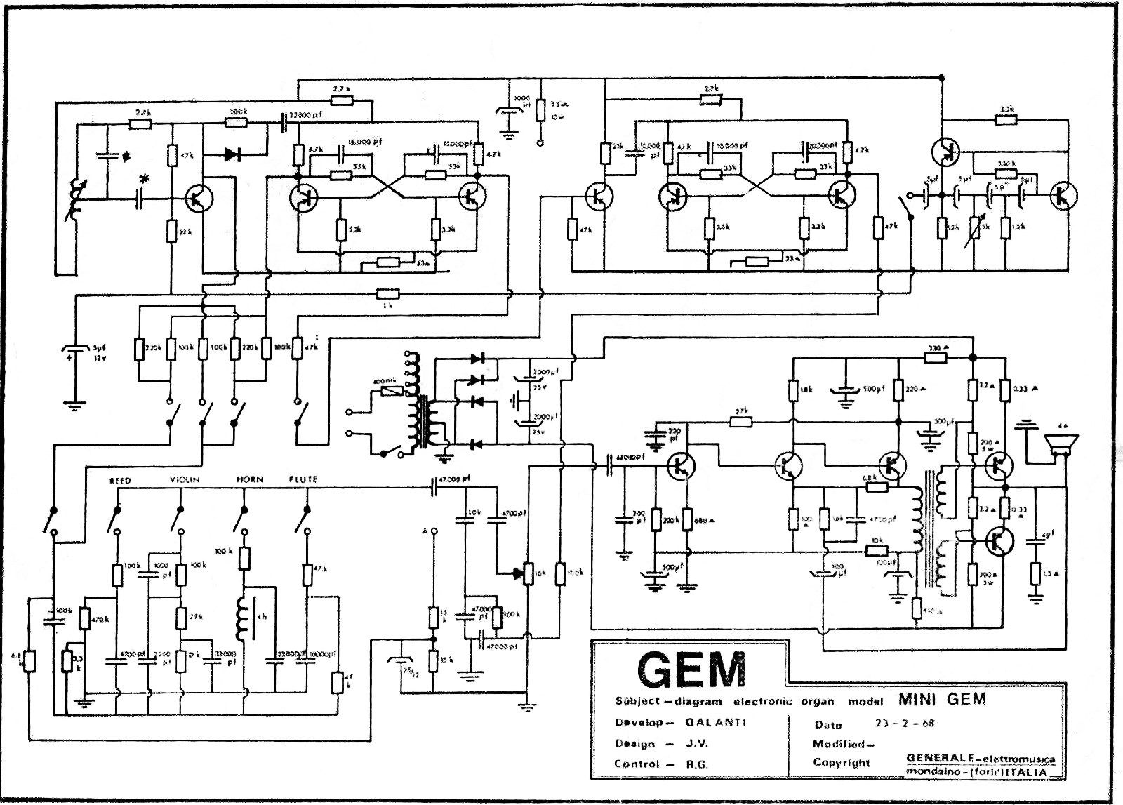
And the Jumbo:
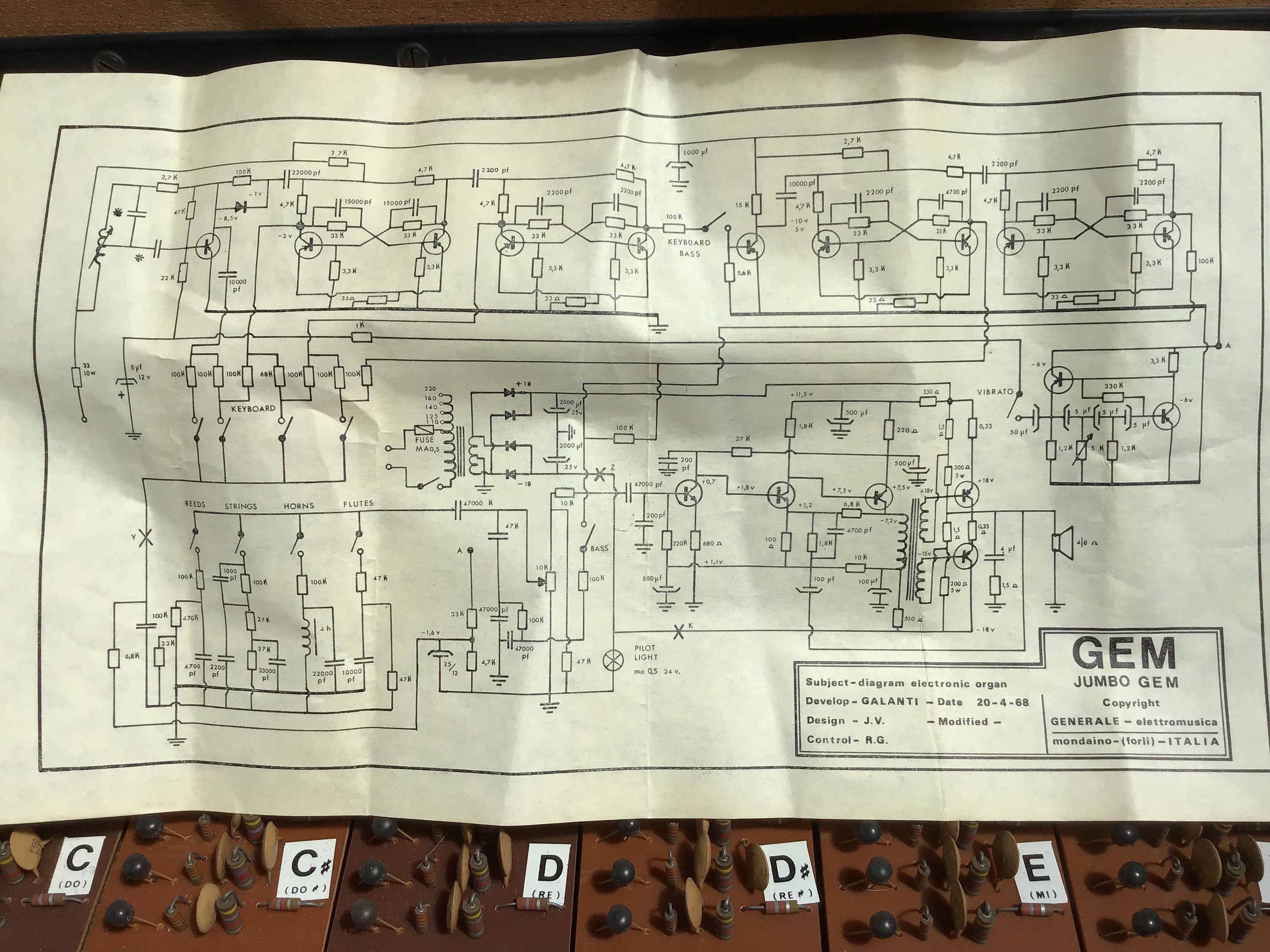
The amplifier circuits (bottom right, the part with 5 transistors and a transformer) are almost identical, but with a bunch of slightly different component values that make it hard to match the resistors and capacitors on the board to the schematic without tracing it all out. So that’s what I did.
Schematic
Here’s the schematic for the amp board on this particular GEMini, which is probably subtly different to yours (pdf version):
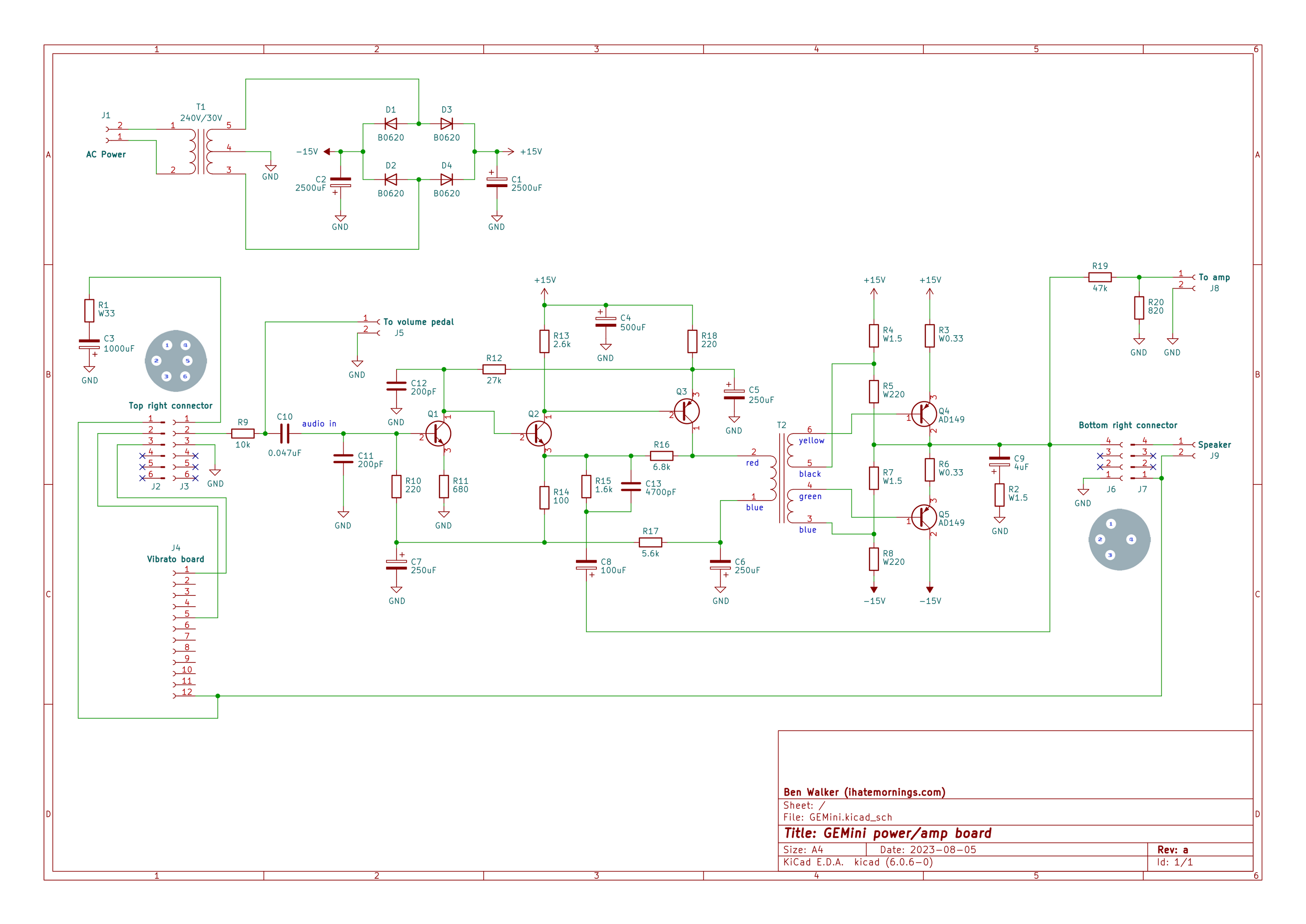
The left hand side with the three transistors is the pre-amp section, and looks quite familiar. The part that I struggle to wrap my head around is the transformer with two secondary windings that feeds the output transistors. I’ve seen amp designs where that sort of transformer feeds a matched pair of NPN and PNP transistors, with one amplifying the positive swing of the audio and the other amplifying the negative, but in this case both transistors are PNP.
I assume there’s something clever going on where the biasing of the transistors and the phase of the incoming signals means that both halves of the audio signal are amplified, but my mental model of PNP transistors isn’t quite there yet. Time to do some more reading…
Saffari: vibrato circuit
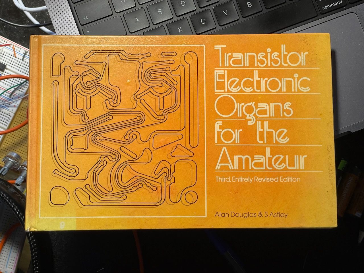
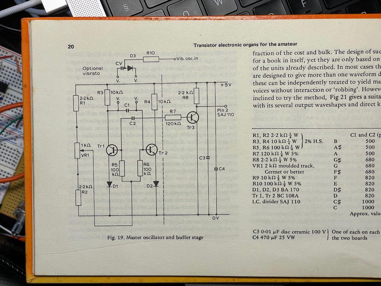
The vibrato circuit for the Saffari was originally based on this one from Transistor Electronic Organs for the Amateur:
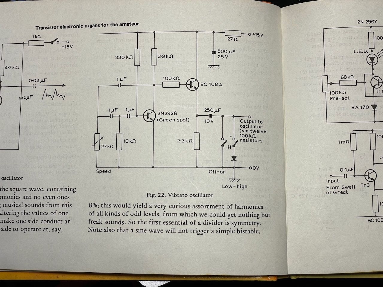
I couldn’t get it to work (maybe my substitute transistors weren’t close enought to the original?) but it looked very much like a Phase-shift oscillator so I tried out some variations on that circuit with the 2N3904 transistors I had and pretty quickly had a beautiful sine wave on the oscilloscope.
Here’s what I ended up with:
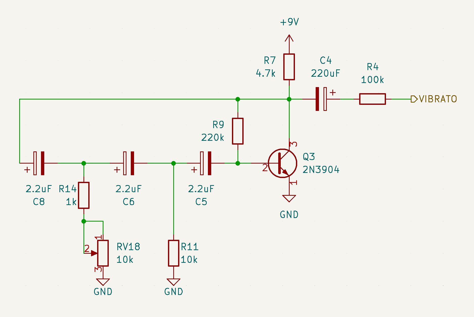
I picked the capacitor values by ear, looking for a reasonable vibrato speed. Putting the resistor and capacitor values into a RC oscillator frequency calculator I get a frequency of about 3Hz (3 cycles per second), which sounds about right. When you turn the vibrato speed knob (RV18) down to zero it gets maybe 5-10 times faster, which is plenty fast for an organ vibrato.
Then I had to figure out how to apply the sine wave to the oscillator circuit to make the square-ish wave into a beautiful vibrating organ tone. That’s for next time.
Saffari: first listen and oscillator details
Yesterday the PCBs arrived for the prototype of my analog transistor organ monosynth and I built it.
It sounded great so I made a little video of my first jam and posted it to Mastodon, where it got some really nice comments.
In theory the oscillator generates a square wave, but because it’s made using a super simple circuit and discrete components (just like the transistor organs of yore) the “square” is actually more like a “chunky asymmetrical blob with rounded corners”. That’s why I love analog synth circuits and that’s why I love the sound of this little creature.
In case you’re interested, here’s the oscillator circuit:
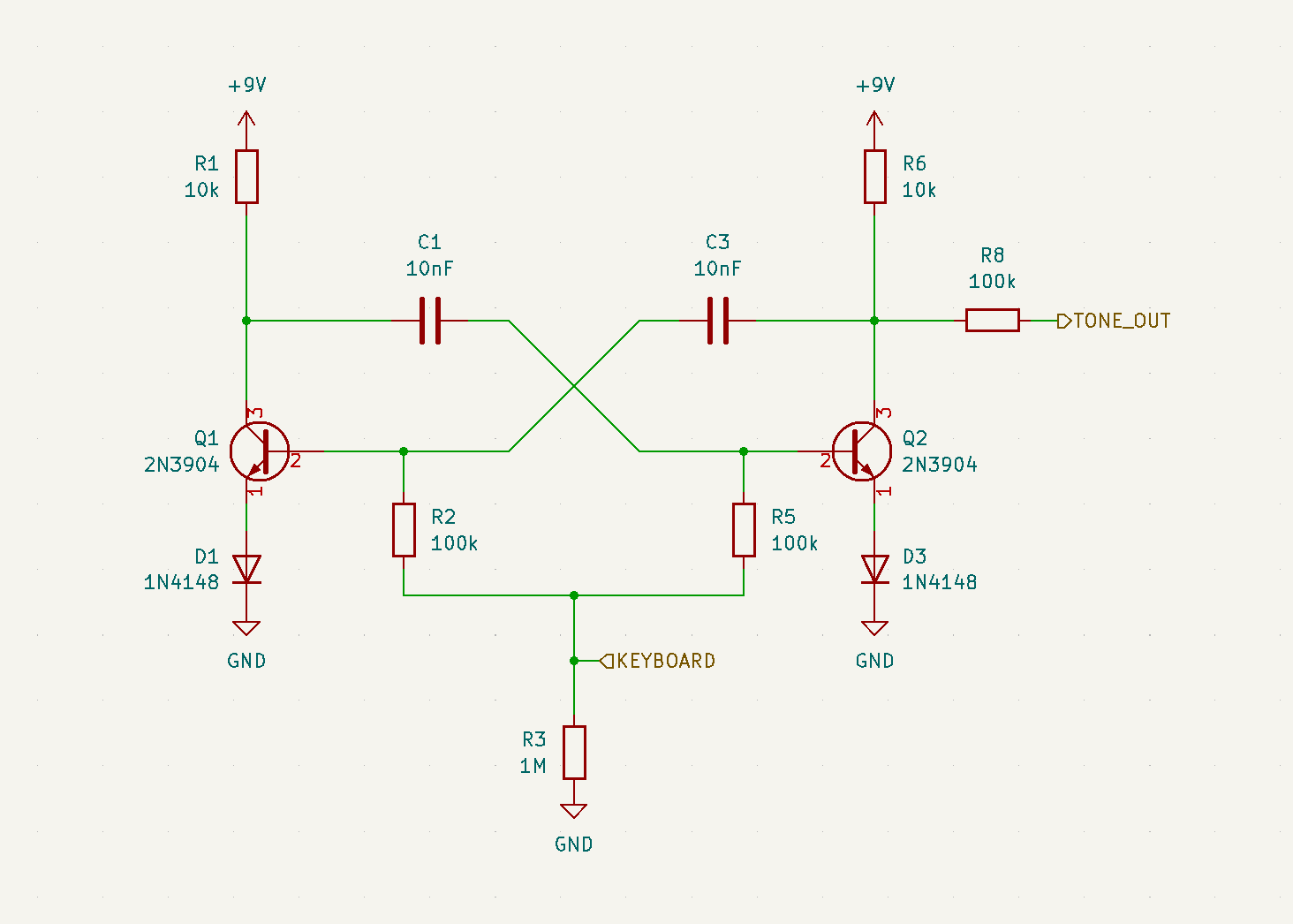
The KEYBOARD input connects through a big old resistor ladder with switches to the 9V rail, so the keys basically vary the voltage at that central point, which in turn varies the frequency of the oscillation. The resistor ladder idea comes from the Pif synth and the oscillator circuit is from Transistor Electronic Organs for the Amateur, a coffee table classic:
That diagram contains a hint as to how I added the all-important vibrato, but I’ll write that up another time…