Building a transistor organ monosynth
“What’s the synth you’re working on?”, asked nobody at all after reading my post about PT2399 filters. Good question!
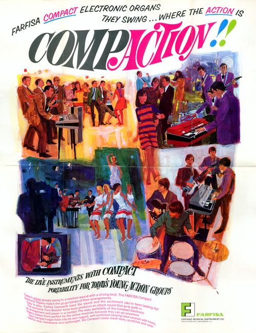
I’m a keyboard player. Piano originally, then organs (Hammond, Farfisa), then synths.
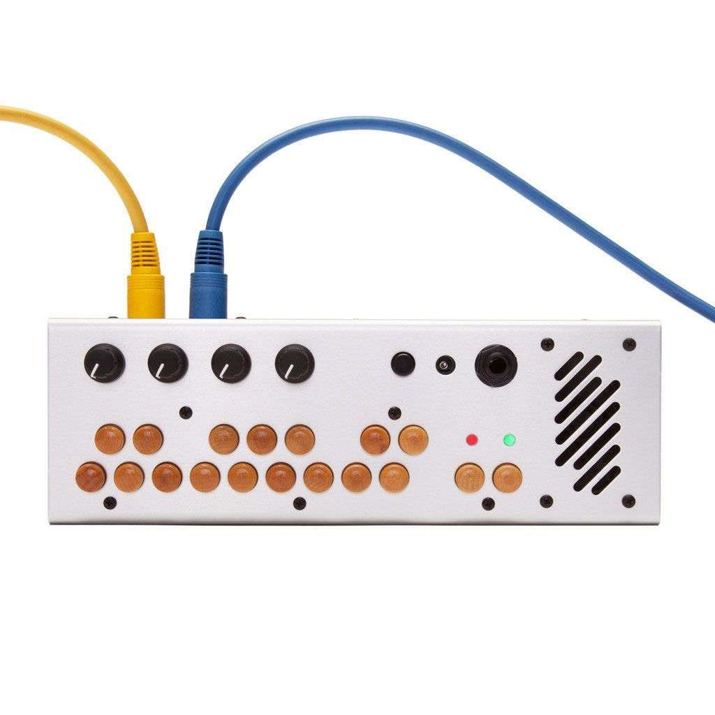
I am also mildly obsessed with the Pocket Piano by Critter & Guitari. It is a tiny digital synth with charming wooden buttons that sounds unlike anything else I’ve ever played. It has several modes (I could write a book about the arpeggiator), but the one I insist on using on almost everything is RED (the one where the LED is red). It’s the basic polyphonic synth mode. It has four sounds, and one of them is a fizzy buzzsaw that cuts through any mix and spreads joy around the room. Combine it with the two-octave pitch bend knob and you have a dangerous weapon of joy.
The Farfisa “multi-tone booster” sound and the Pocket Piano buzzsaw sound have a lot in common, and it’s the combination of these, along with a video about a quirky Soviet toy keyboard, that inspired me to start building a transistor organ monosynth back in July.
I’ll post more about the circuit and how it all works (and sounds!) another time. I’ve designed a PCB and ordered all the components so I’ll have something fun to show in a couple of weeks. It might be the keyboard of my dreams. Or an unusable monstrosity. Only time will tell!
Making sense of the PT2399 filters
I’ve been playing with the PT2399 (every DIY guitar pedal maker’s favourite lo-fi delay chip) for a couple of years now, and I still find myself confused by the filters and pinouts. The canonical PT2399 Analysis by Electrosmash was a great help in getting my head around how to use the chip, but I find it difficult to match their re-drawing of the block diagram to the jungle of resistors and capacitors sitting next to the chip on my breadboard.
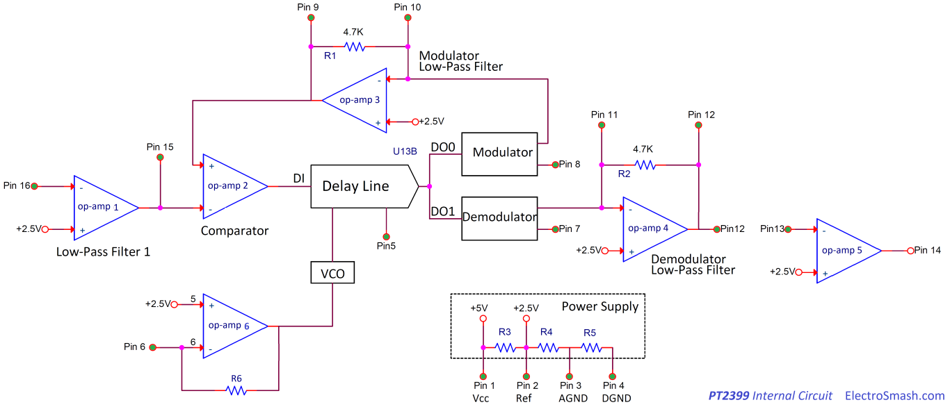
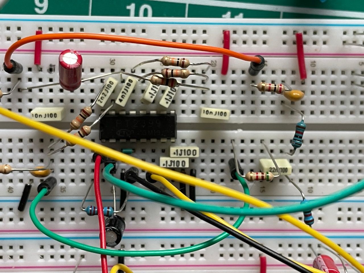
I’d like to be able to understand what’s going on so I can experiment with the sound. So I did my own re-drawing of a simple delay circuit, with the PT2399 clearly represented by a dotted line rectangle and just enough of the internal block diagram to make sense of how the filters work.
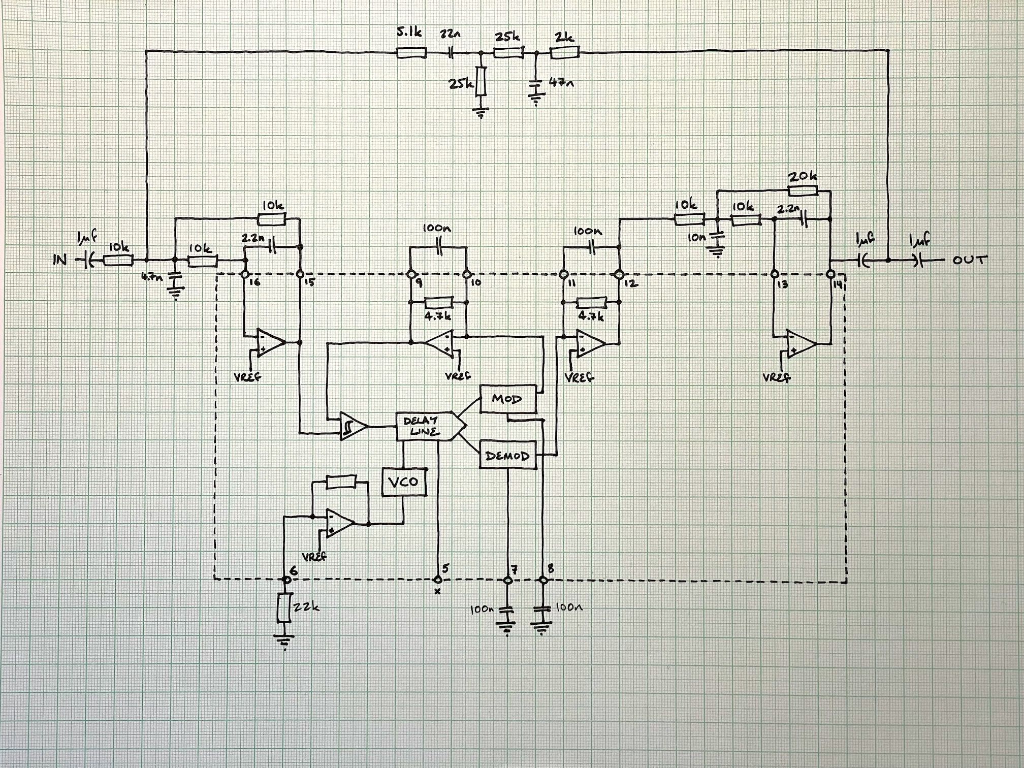
The circuit is pretty much the ECHO example circuit from the datasheet, but I may have used some of the revised values from the Sea Urchin / Deep Blue Delay version. I included the feedback path, but left out the dry/wet mixer — this just shows a dry signal coming in and the delayed signal coming out.
Drawing it this way makes a few things clear to me:
- Pin 16 is the input of the delay chip, pin 14 is the output (assuming that we’re using the filters as recommended)
- The input and output filters (16/15 and 13/14) are multiple feedback low pass filters (this calculator helped me figure out how they work)
- The modulator and demodulator filters have a built-in resistor, which is why they only need a capacitor outside the chip.
I added some notes about the filter values and a few other handy hints:
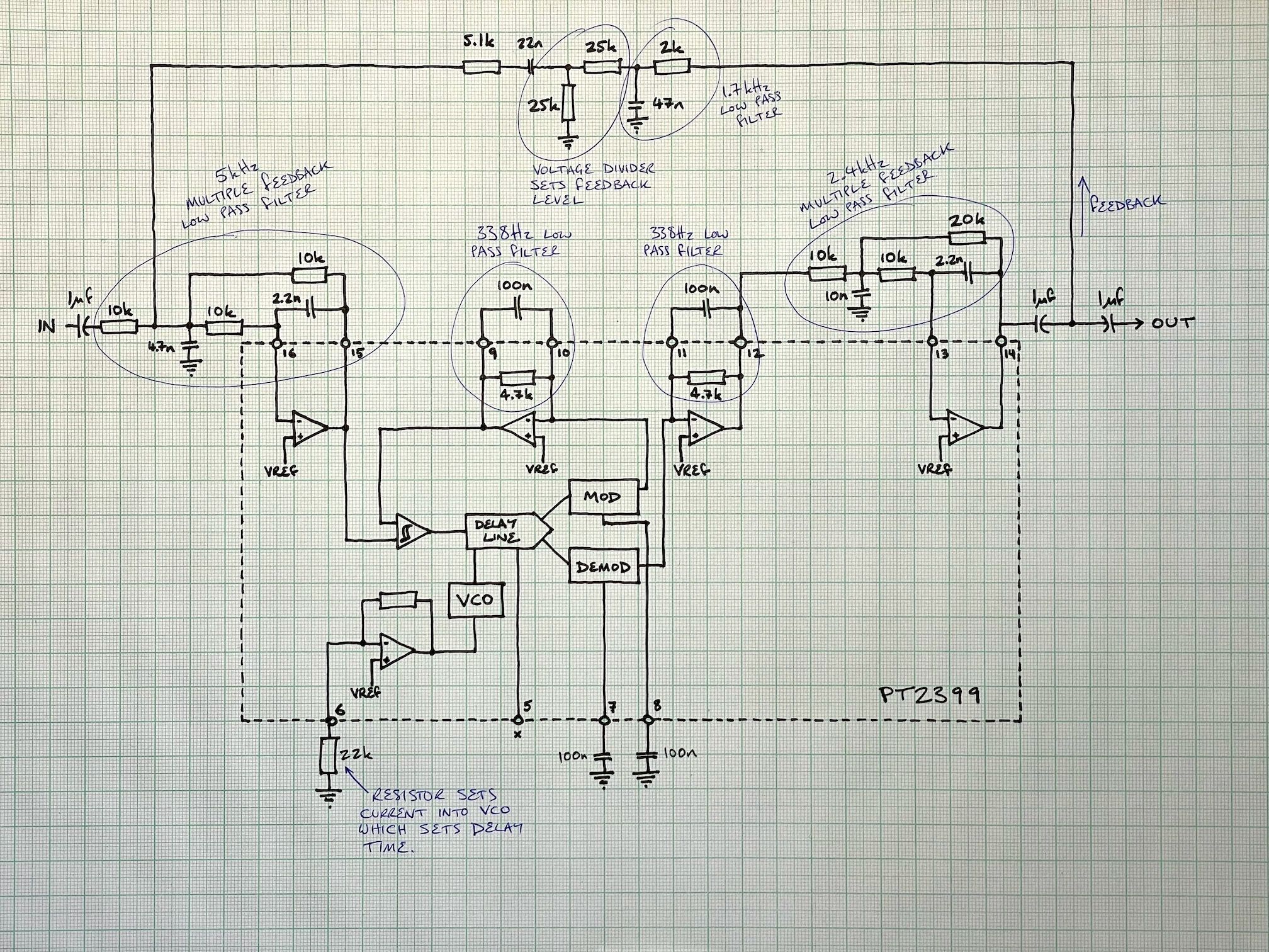
It’s probably worth noting that the two 338Hz low pass filters aren’t really filtering the audio — they’re filtering the digital output of the MOD and DEMOD blocks, which use Delta-sigma modulation to convert an analog audio signal into a series of digital pulses. The filters smooth the pulses back into an analog signal (or something like that — I’ve tried to get my head around how it works several times and still don’t quite get it).
But the 2.4kHz low pass filter on the output and the 1.7kHz low pass filter on the feedback path are up for grabs — changing their cutoffs can change the sound of the delay quite dramatically. I dropped the output filter down to 1.6kHz on the synth I’m working on now and it sounds smooooth, even with longer delay times.
Simon Says
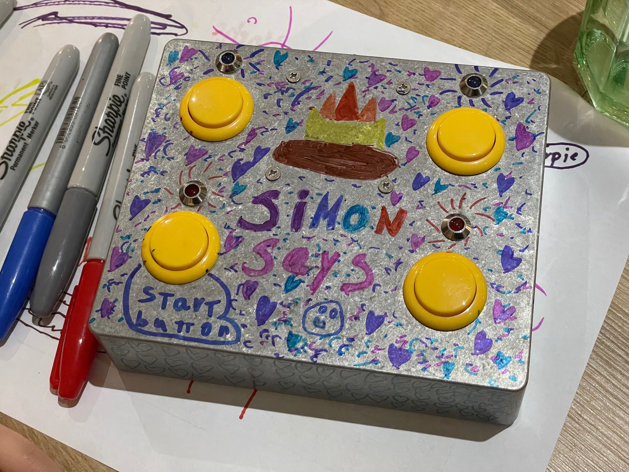
I made a Simon Says toy with Clem over a couple of weekends. Started with an OKdo project and customised the code to fix some quirks and add our own musical touches (it plays Nazareth from Nativity (2009) every few levels).
We built it in a metal guitar pedal case using some arcade buttons and a speaker I had lying around from audio.computer experiments. It turned out to need a lot of wires, but that was a good excuse to teach Clem how to use a wire stripper and a soldering iron. Useful life skills…
I put our code up on Github in case anyone is tempted to tinker.
Fame at last!
Beanie Tapes was featured on Bandcamp’s November Tape Label Report. What a treat!
One might call Oxford’s Beanie Tapes the ultimate Bandcamp tape label.